Rebuilding the Hatch
November 20, 2025
Having a baby means you probably have a sound-machine. When that baby grows into a toddler, that means you likely also have things break pretty often and being an engineer means I am always fixing these broken things.
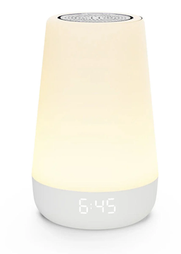
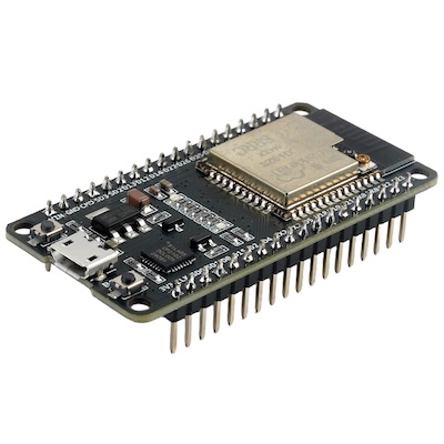
Our Hatch, an IoT device for white noise and night light, broke a few months ago. The device wouldn't turn on at all, regardless if it was on battery or plugged in directly. So, I opened it up to debug what the issue was. Using my multimeter I was able to verify that there was power being supplied to the board, the speaker worked, and the LED strip also worked. The one thing that did not seem to work was the PCB. Nothing seemed to be burned out or noticibly wrong with the PCB, but I did notice that it was labeled. It was a "espressif esp32" board, and this immediately triggered my memory because I had heard about these ESP32 devices, they are low-cost microcontrollers with WiFi and Bluetooth.
So like any engineer, I figured I could just re-create the Hatch with my own ESP32 and write some custom software. Instead of getting a new Hatch, which is about $120, I purchased an ESP32 for $8 on Amazon.
So I ripped out the old PCB in the Hatch and with my new ESP32 I was able to connect the existing LED strip, speaker, capcitive touch ring, and battery components in the Hatch. I noted the pin-outs of these components that I connected with simple wires to the ESP32. I then used PlatformIO IDE in VSCode and started to write out some Arduino code to control these components.
The code was realtively simple, it was a couple hundred lines of code, most I was able to generate and verify via ChatGPT. After writing the code, I could flash the ESP32 directly from VSCode. The most challenging part was getting the speaker to produce a similar white-noise as the existing Hatch, this involved debugging frequencys and also having to get a small amplifier chip to make the voume loud enough.
This is an example of how to configure the I2S peripheral to output white noise:
void i2sInit()
{
  i2s_config_t cfg = {
      .mode = (i2s_mode_t)(I2S_MODE_MASTER | I2S_MODE_TX),
      .sample_rate = SAMPLE_RATE,
      .bits_per_sample = I2S_BITS_PER_SAMPLE_16BIT,
      .channel_format = I2S_CHANNEL_FMT_RIGHT_LEFT,
      .communication_format = I2S_COMM_FORMAT_I2S,
      .intr_alloc_flags = 0,
      .dma_buf_count = 8,
      .dma_buf_len = 256,
      .use_apll = false,
      .tx_desc_auto_clear = true,
      .fixed_mclk = 0};
  i2s_pin_config_t pins = {
      .bck_io_num = I2S_BCLK,
      .ws_io_num = I2S_LRC,
      .data_out_num = I2S_DOUT,
      .data_in_num = I2S_PIN_NO_CHANGE};
  i2s_driver_install(I2S_NUM_0, &cfg, 0, NULL);
  i2s_set_pin(I2S_NUM_0, &pins);
}
All in all, it took me about 4 hours of work to program and test and it effectively does the exact same thing as before. I spent about $15 total on the ESP32, wires, and amplifier chips compared to $120 for the new device. I additionally learned a ton about memory constraints on the ESP32 and how to get these physical components all wired up. It was a really fun challenge and I enjoyed the hands-on nature of working with some hardware and components and seeing my code actually come alive as I interacted with the device.